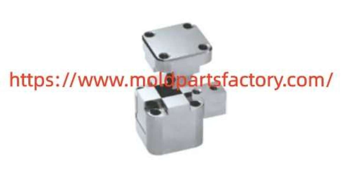

Side Core Pulling remains a practical solution when plastic components contain undercuts holes or recesses that do not align with the main opening direction of the mold. Selecting the right system depends on the geometry of the part the expected production volume and the available machine capacity. Different structures address external features internal recesses multi direction undercuts and deep lateral details in distinct ways. Understanding these differences helps mold designers and production teams choose an approach that supports smooth release consistent cycles and reasonable maintenance demands.
Mechanical angle pin driven structures suit many external undercuts and moderate depth recesses. An angled pin engages a sliding insert during mold opening and drives the insert outward in a controlled path. This arrangement works well for medium sized features on consumer goods housings and automotive interior parts where the required travel distance stays within typical pin limits. The structure remains relatively compact and relies on the natural motion of the mold so it needs no extra power source. Careful attention to pin angle length and wear surfaces keeps movement reliable over repeated cycles.
Hydraulic cylinder actuated inserts handle longer travel distances and higher force requirements. These prove useful for deep external recesses large internal undercuts or parts that demand precise sequential motion. A hydraulic cylinder mounts outside the mold and connects to the sliding insert through a linkage or direct rod. The independent power source allows the insert to move before full mold opening or after ejection begins which reduces interference risks. This style fits larger industrial components appliance housings and structural parts where mechanical pins alone cannot supply enough stroke or force. Proper sealing hose routing and pressure control help maintain stable operation in continuous production.
Combined mechanical and hydraulic arrangements address multi direction undercuts or features that require staged motion. One insert may travel on an angle pin while another moves under hydraulic control. Delay mechanisms such as elongated holes or timed valves ensure the inserts clear the part in the correct sequence. These structures appear in complex housings connector bodies and multi cavity tools where several undercuts exist on different faces. The added flexibility supports tighter part designs yet demands careful layout of space for cylinders linkages and sensors.
Pneumatic options serve lighter duty applications or situations where hydraulic fluid is less desirable. Air cylinders provide quick response and clean operation for shallow external features on smaller components. They integrate easily into existing mold frames and suit lower force needs. For higher precision or heavier loads hydraulic remains more common. In all cases the choice considers the material shrinkage rate ejection force and available platen space so the selected structure fits both the part and the press.
Part geometry guides the final decision. Shallow external undercuts often pair well with simple angle pin slides. Deep or internal recesses typically call for hydraulic or multi stage motion. Multi face undercuts benefit from combined systems with sequenced timing. Production volume also matters. High volume tools favor robust wear resistant materials and easy access for maintenance. Lower volume or prototype tools may accept simpler hand loaded inserts when automation costs outweigh the benefits.
Material selection for the sliding inserts and guide ways influences service life. Hardened steels with proper surface treatments resist wear from repeated contact. Adequate lubrication channels and dust protection extend intervals between service. Clearance between the insert and cavity wall must accommodate thermal expansion while preventing flash. Regular inspection of wear surfaces and retention features helps maintain dimensional stability of the molded part.
Moldpartsfactory supplies a range of mold bases inserts and actuation components that support these different structures. Engineers can review standard slide units angle pins hydraulic cylinders and custom linkages to match specific part requirements. Careful coordination between part design and mold layout reduces the risk of binding incomplete release or excessive cycle time.
When planning a new tool start with a clear map of every undercut location depth and direction. Calculate the required travel force and available space inside the mold frame. Test the motion sequence in simulation software before cutting steel. Validate the release path with early sample parts and adjust timing or clearances as needed. These steps help the chosen structure perform consistently across production runs.
Visit https://www.moldpartsfactory.com/ to review available mold components and discuss how different actuation styles can support your next set of part designs.