High-traffic access points demand a delicate balance between vehicular throughput and pedestrian safety. Commercial parking garages, residential complexes, and industrial checkpoints depend on perimeter security gates to control vehicle access. The global automatic boom barrier market reached a valuation of $2.8 billion in 2025 and will reach $5.6 billion by 2034. This growth shows an 8.1% compound annual growth rate. However, the proliferation of automated access equipment increases the risk of mechanical crushing incidents.
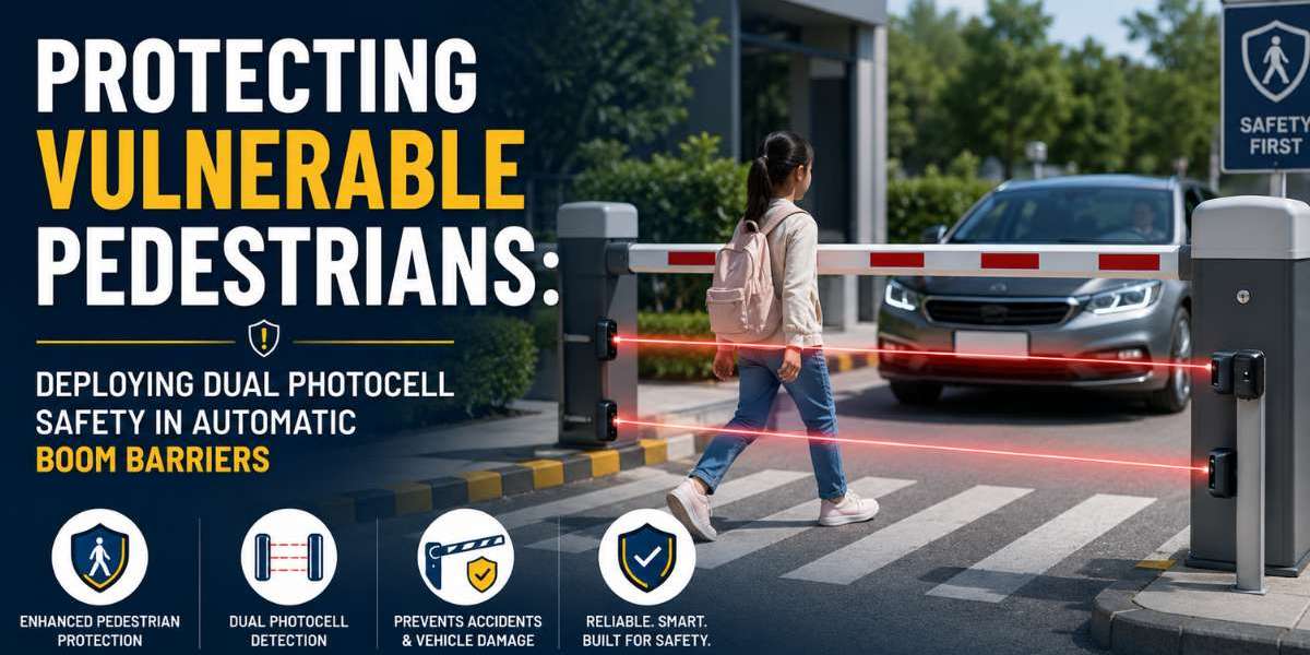
A standard Automatic Boom Barrier exerts significant downward kinetic force during its closure cycle. While legacy detection systems protect oncoming vehicles, they frequently fail to detect smaller, vulnerable pedestrians. Implementing a dual photocell infrastructure transforms an Automatic Boom Barrier System from a vehicle-centric checkpoint into a safety-compliant perimeter asset.
The Vulnerability of Pedestrians at Vehicle Checkpoints
Vehicle access lanes present severe physical hazards for pedestrians, children, and individuals with limited mobility. Historical safety data compiled by global consumer product safety groups highlights the inherent risks of automated gates. Over a multi-year tracking period, researchers identified thousands of emergency room injuries related to automatic gates, including several fatalities. Children under the age of 15 accounted for a significant portion of these crushing injuries.
The primary hazard stems from a fundamental design limitation in traditional access control layouts. Most entry lanes utilize inductive magnetic loops buried beneath the asphalt. These loops operate on electromagnetic induction principles:
Metal Detection: The system detects large metallic masses like cars, trucks, or motorcycles.
Pedestrian Invisibility: The system fails to register human presence, as pedestrians carry no inductive metal mass.
Premature Closure: The gate arm descends immediately after a car exits, striking any pedestrian walking closely behind the vehicle.
Furthermore, a descending aluminum or fiberglass barrier arm can strike a person's head or neck with hundreds of pounds of force. This mechanical impact causes severe concussions, lacerations, or bone fractures. To eliminate this liability, access engineers must install non-contact optical sensors that monitor the entire path of the barrier arm.
Technical Limitations of Single Photocell Systems
Many facility managers attempt to resolve pedestrian hazards by installing a single infrared photocell sensor. A single-beam system consists of a transmitter that projects a continuous infrared light beam across the driveway to a receiver unit. If an object breaks the beam while the barrier arm descends, the control board triggers an auto-reverse loop to open the gate.
While a single photocell provides basic protection, it contains critical blind spots. Standard installation guidelines place the single beam at a height of 30 centimeters to 50 centimeters above the ground. This specific height aligns with a standard vehicle bumper or tire rim.
Unfortunately, this narrow beam placement fails to account for human anatomy. A tall pedestrian can easily step over a low-mounted 30-centimeter sensor beam. Conversely, a child can walk completely underneath a higher-mounted 60-centimeter sensor beam. In either scenario, the core controller receives no obstruction signal, causing the Automatic Boom Barrier to continue its downward descent.
Environmental interferences also compromise single-beam reliability. Heavy rain, dense fog, blowing snow, or direct sunlight can cause optical misalignment or beam blinding. If a single sensor malfunctions or suffers a power loss, the entire safety layer drops, leaving the entry lane unprotected.
Architecture of Dual Photocell Systems
Deploying a dual photocell architecture removes optical blind spots by establishing two distinct layers of non-contact detection. This system mounts two separate transmitter-receiver pairs at different heights on the vertical plane of the entry lane.
The physical separation between the two beams ensures total coverage across the path of the barrier arm:
The Low-Level Photocell: Installed at a height of 30 centimeters above the pavement. This sensor detects small children, pets, stroller wheels, and low vehicle bumpers.
The High-Level Photocell: Installed at a height of 90 centimeters to 100 centimeters above the pavement. This sensor detects the torsos of adult pedestrians, cyclists, and taller commercial vehicles.
The two photocell pairs connect to the control board via separate input channels or a supervised safety relay. The system logic uses an "OR" gate configuration. If either the low-level beam OR the high-level beam breaks during the closing cycle, the controller stops the motor instantly. The system then commands the drive gears to reverse direction and return the arm to a fully vertical position.
Integration with the Control Board
Integrating safety sensors requires a clear understanding of low-voltage electrical circuits. Industrial Automatic Boom Barrier System controllers feature dedicated safety terminals labeled "Photocell," "Safety Input," or "GND." The dual photocells utilize fail-safe wiring topologies to prevent common mechanical blind spots.
Control Terminal Label | Wiring Strategy and Electrical Function |
24V AC/DC Power Output | Provides continuous power to optical sensor boards |
Common (COM) / GND | Serves as the ground return path for the safety loop |
Safety Close (NC Input) | Breaks the circuit to trigger immediate arm reversal |
Photocell Test Terminal | Executes a sensor diagnostic pulse before each motion |
Engineers configure the safety contacts as Normally Closed (NC) circuits wired in series loop formations. In a Normally Closed configuration, a continuous electrical current flows through the sensor relays back to the main control board. When a pedestrian steps through either infrared beam, the corresponding internal relay drops open, breaking the circuit loop.
This configuration provides immediate fail-safe operation. If a wire breaks, a terminal rusts, or a sensor loses power, the loop opens automatically. The controller interprets this loss of continuity as a permanent obstruction, preventing the barrier arm from moving downward. The system stays locked open until a technician repairs the circuit, protecting pedestrians from hardware failures.
Overcoming Environmental Challenges
Outdoor access lanes expose optical safety sensors to severe weather conditions. Moisture accumulation, dust coatings, and direct sunlight create operational challenges that cause false alarms or sensor blinding. Industrial field teams use specific engineering strategies to maintain high system reliability.
Sunlight blinding occurs when direct solar radiation overpowers the infrared receiver diode, mimicking a clear beam path even when an object blocks it. To counter this, manufacturers modulate the transmitter's infrared signal at a specific frequency, such as 38 kilohertz. The receiver uses internal band-pass filters to ignore static ambient sunlight, reacting only to the matching modulated frequency.
Technicians install weather-proof polycarbonate hoods over the sensor housings to deflect rain droplets and blowing snow. Condensation or frost on the lens can scatter the infrared beam, creating false obstruction signals. High-end photocells feature internal miniature heating elements that activate automatically when ambient temperatures drop near freezing. These heaters keep the optical lenses clear, ensuring uninterrupted pedestrian protection year-round.
Coordinating Safety Loops and Photocell Zones
A reliable security entrance requires the seamless coordination of multiple sensor types. While dual photocells protect vulnerable pedestrians, underground inductive loops handle vehicle detection. Combining these technologies prevents accidental vehicle strikes and stops tailgating attempts.
The control unit processes data from the dual photocells and the magnetic loops through a structured sequence. When a vehicle approaches, it triggers the first inductive safety loop, causing the Automatic Boom Barrier to open. The vehicle then passes through the dual photocell zone and crosses the second inductive loop, known as the closing or "shadow" loop.
The system will not close the gate arm if any sensor detects an object in the path of travel. If a car stops directly under the barrier, the inductive loop holds the gate open. If a pedestrian walks behind that vehicle, they break the dual photocell beams, extending the open time. This layered sensing architecture ensures that the gate reacts correctly to changing traffic scenarios.
Compliance with Global Safety Standards
Deploying dual photocell sensors helps facilities comply with international gate safety regulations. Regulatory bodies enforce strict performance rules for automated access points to minimize public injury risks.
The European standard EN 12453 and the American standard UL 325 define specific requirements for vehicle gate safety. These standards classify an Automatic Boom Barrier System as an automated machine, requiring secondary non-contact safety devices if the general public can access the area.
Compliance mandates specific operational behaviors:
Pre-Flight Testing: The control board must send a diagnostic pulse to verify photocell functionality before starting any downward motor movement.
Force Limitation: If a primary sensor fails, the mechanical crushing force must remain below 400 Newtons, and the gate must reverse within 0.75 seconds of impact.
Visual Warning Signals: The barrier arm must incorporate integrated LED strip lighting or flashing beacon indicators to warn pedestrians of imminent movement.
Installation and Maintenance Protocols
Improper installation can ruin the safety benefits of an advanced dual photocell system. Installers must mount the transmitter and receiver pillars on solid concrete foundations. Structural shifting from loose soil or heavy vehicle vibrations causes optical misalignment, resulting in intermittent system lockups.
Technicians use specialized alignment tools, including integrated alignment LEDs or optical viewfinders, to center the beams across wide driveways. Wire runs must utilize shielded, outdoor-rated low-voltage cables routed through rigid conduits. This shielding protects the sensor lines from electromagnetic noise generated by nearby high-voltage power grids.
Regular preventative maintenance preserves long-term system safety. On-site staff should wipe dust and road grime from the sensor lenses on a monthly basis. Technicians must conduct manual walk-tests by breaking the high and low beams with a test card to confirm the auto-reverse function works perfectly. Documenting these regular checks protects facilities from legal liability in the event of an access lane accident.
Conclusion
Securing modern facility perimeters requires a data-driven approach that prioritizes human safety alongside vehicular control. Traditional vehicle tracking tools like magnetic loops cannot protect children or pedestrians from heavy machinery. Upgrading a facility with an advanced Automatic Boom Barrier helps manage traffic flow while reducing structural liability risks.
Integrating a dual photocell layout removes dangerous optical blind spots at different heights. This sensor deployment ensures that the control system identifies both small children and adult pedestrians before a crushing impact happens. Fail-safe wiring loops and modulated infrared signals maintain high system reliability through severe weather conditions.
Investing in a dual-beam Automatic Boom Barrier System protects property owners from expensive injury claims and ensures long-term compliance with global safety standards. This balanced approach helps organizations construct a secure, efficient, and accident-free perimeter entry point.